Replace your main fuse panel
- joepampel
- Jun 27, 2022
- 7 min read
Updated: Mar 3, 2025
One of my goals is to feel good about taking the car for medium length trips, weekend sort of things, a few hundred miles each way. Part of feeling good about that is making sure that I don't need to pack oddball parts like ceramic fuses. They don't have any unique characteristics and just make things complicated when the whole world has standardized on blade fuses eons ago. 1976 is when they were introduced, says Wikipedia. That's long enough.
So how do we get modern blade-style fuses into an old car? Fortunately there are companies making replacement fuse panels which are 1:1 replacements. The panel I bought even has built in headlight relays. #Winning

Here are the new panel and old panel plus my semi-janky headlight relay setup. A new panel with relays was always part of the roadmap so I knew this was a temp setup.
In general, auto wiring is generally very simple and repetitive. You loop from + on the battery to ground (chassis or - on the battery) with some device or system in line. The car is really just a series of loops in parallel. The hot side (top) of the fuse panel is where power enters, and then it leaves the fuse panel from the bottom to go to the load; whatever it is we are operating. Fuses are there in case something goes wrong and that load draws too much current - without fuses we could fry our wiring. All wire has a current rating that comes down to how much heat it can take, which is a product of the current it is carrying plus if it is out in the open or tied up in a bundle (where it can't easily get rid of heat). And take it from someone who has been there; setting your dash on fire on a hot date is not a good look.
The simple way to think about this mass of wires:
The top supplies power, either switched or unswitched to a terminal (or terminals)
The bottom delivers fused power to a specific circuit or circuits.
If something is on all the time, it is getting unswitched power. That's easy to ID.
If something turns on from the wrong switch, you can track that down pretty quickly too.
And if you blow fuses, you probably have a short.
Tools:
13mm cresent wrenh for battery terminal
Small screwdriver - for terminals as well as to help push connectors into terminals
Phillips head - for mounting screws
Needlenose pliers - to pull slack on wires, and to shape the ends so they fit
Awl - to locate mounting holes through the rubber foam backing pad, and to open up terminals for additional leads.
DMM - to measure continuity, resistance or voltage as needed.
Process
First I compared the old panels to new and make sure the wiring points all tie out.
I referenced both panels to the diagrams in the Bentley manual and the factory diagram. There are extra spots on the old panel - they are just extra connection points because of the number & size of the wires. I need to make sure everything will fit.
If everything ties out on paper we can begin our work. A place for every wire, and every wire in its place. That is the goal. Step one will always be disconnecting the battery.
Next, the panel mfr recommends tie wrapping new on top of old and then moving wires over one at a time.
I wound up not using the zip ties. You would need to loosen all of the screws ahead of time and I was concerned about wires coming out when I was not ready for them.
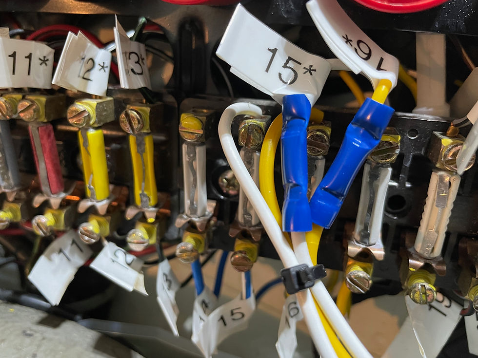
I was a bit OCD; I printed labels for leads 11-21 and I took a bunch of pictures. I compared my photos to the 1986 fuse panel diagram (below) to see if there were any gotchas, and there weren't. I am red-green color blind so the pics are of limited good when it comes to certain colors so I needed backup.
It's only 21 connections on top and again on bottom. The answer to the universe, 42! Just go one at a time, be very careful not to lose any wires behind the board or move them over a spot, and you should be fine.
Step 1: Labelling
I have chosen to label for a few reasons here. First is I am RG color-blind. Photos and diagrams will only do so much good: I need more. Second, I want to spot problem areas ahead of time. For example, there are 21 positions top & bottom on the new board. But the old board has extra spots, and does not follow any kind of "one wire per hole" convention. There are several spots with multiple circuits sharing a terminal that can be a tight fit.
Labelling doesn't take long, and in the end helped me spot a mistake I made faster.

Exactly 42 connections, on paper. Read into that what you will.
This is an example of the "fun part". The first 3 positions (going L to R) look ok, 1 position with 1 wire. ok. But look at the 4, 5 & 6. They are shorted together to make one big terminal for 5 wires. (and shorted to 2 & 3 as well by those copper straps). The straps are sharing an "always hot" connection to the battery and are a handy way to orient the board in your mind. There are several spots on the panel that do this to help reduce the number of wires required, saving weight, harness cost and assembly time.
I recently purchased a copy of the factory diagram for the fuse panel on a 1986 3.2 Carrera (US model) and it is likely close enough to what you are looking at. I have added it below. The factory panel can be confusing with fuses that are jumpered to other fuses - or even not connected. It's not complicated, it's just lots of details. I overlapped the 3 pages so you can combine them into one big one if you want to. If you zoom in a little when printing it will be "actual size".
The bottom of the diagram is the top of the fuse panel. You'll be able to tell by the jumpers on the windshield facing end. Go slow, take your time. I started with the right hand side and started with the bottom connections. The bottom right is the most difficult area both because of the thick wires but also because of the poor visibility.
Process-wise here is how I did it:
Don't install the fuses ahead of time; they will just be in the way.
Disconnect the battery at the negative terminal and make sure it can't connect.
Unscrew all of the screws holding the old panel to the car
I clipped out my temporary headlight relays. (as needed)
I worked right to left across the bottom of the panels and then did the same across the top. ("right" meaning closest to the windshield)
What makes it tricky is some of the connections barely fit and the leads have very little slack in them. Having the new board loose let me pivot it towards the old connections, both getting it slightly closer as well as helping visibility. You should also plan to wear sweats or other soft clothes with no metal on them; you'll probably wind up leaning over the fender for a few hours.
Pics:
I started with the rear fuse panel for practice.

Mrs P had some old yellow nail polish, so I used that to give it a bit of 'factory' look and help prevent the screws from backing out.
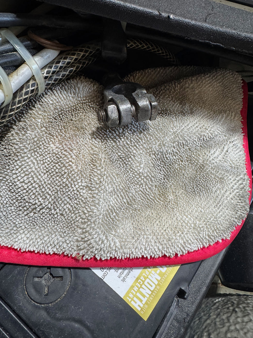
A shop towel works well for keeping the negative terminal from touching anything it shouldn't
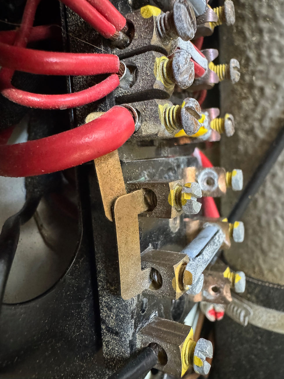
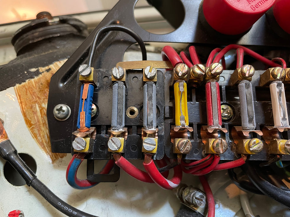
The old terminals are a bit rusty, and a little crowded. The shorting bars are just getting unswitched battery power to all the things that need it. (right side, upper)

What you get when you tie wrap. The terminals line up pretty well in general, and if you loosen all of the old terminals first and have enough slack it can be a good method to try.

Here I am getting started on the lower right side of the board. As all of the leads are removed from the old panels, each can be slid out to give you more room to work.
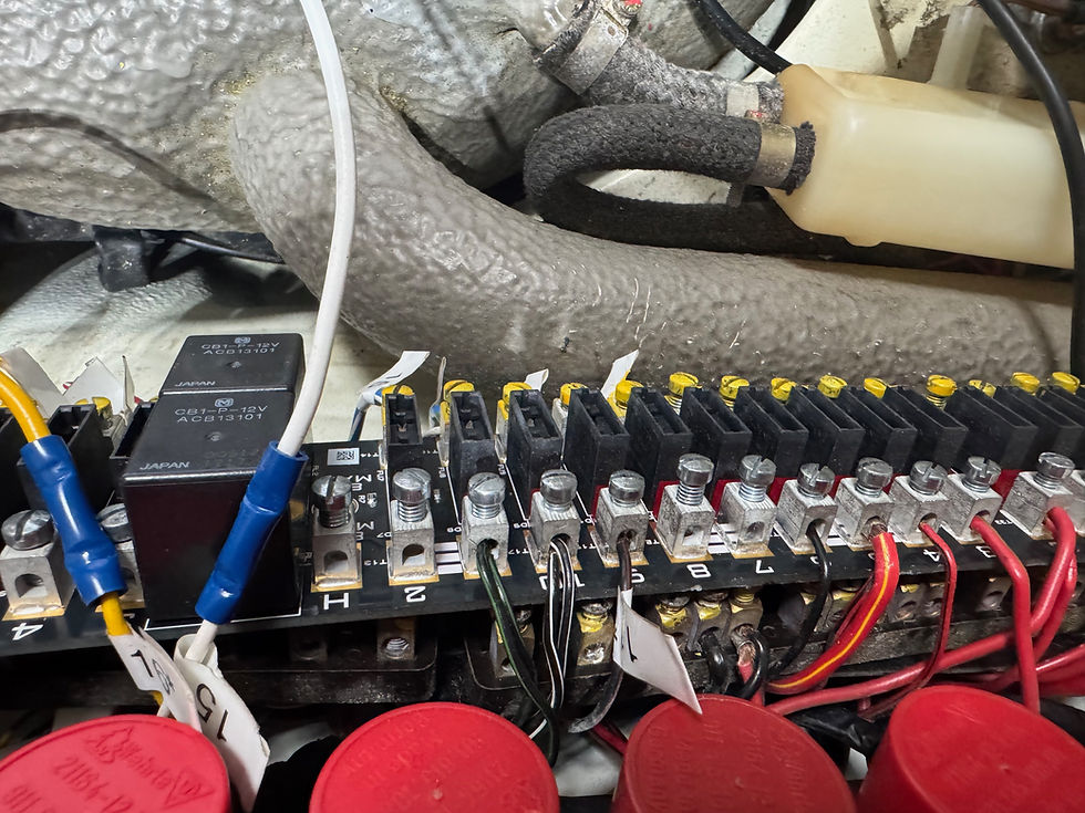
Here is where I goofed and the labels helped. In the pic I have lead 11 over 1 too far which caused those paired wires to its left to be in the wrong terminals. They are for the turn signals, and you can see the one furthest left is stuck into a headlight terminal (1 & 2 are bussed together - those stripes) for the high beams. Position 8 on the board is the 11th wiring position - which I had also marked on the wiring diagram. Printing a copy of the diagram and checking stuff off as you go is a practice that I find helpful.

Here I'm all done. I re-used the 12ga red lead from the battery to power the H4 headlights using the "H" terminal. I made sure the ground from the mounting screw below it was good, otherwise I could have re-used my ground from the temp headlight wiring. The high beam lead (white) is a bit short, I may go back and clean that up.
Make sure that your lower leads are not blocking the brackets that lets you snap the fuse panel cover on.
The last bit is to test, make sure all the things still turn on and work. Windows, lights, etc. Be methodical, there isn't enough slack for these wires to get very far off course, and the diagram (below) is a great reference for what should be where.
This job took most of a Saturday for me, probably 5-6 hours all in. And now my back & legs are sore from bending over the fender the whole time. So maybe I should add Tylenol to the materials section? YMMV.
Fuse Panel Diagram: (for MY 1986) The diagram that seems to often be missing from used factory diagram sets, provided here as a public service to help better support the cars we love.
Actual connections will vary somewhat based on the specific options on the car such as factory alarm, rear wiper, headlight cleaners, any "mods" from a prior owner, etc. Factory connections all have crimped ends on them, so you should be able to spot any "bonus" wiring pretty easily. The possible factory connections are all noted here. After checking this against photos from my '88 I think this is probably very accurate for the 86-89 cars.
Classic Retrofit Panels are what I used for this project. Their site includes nice instructions, how to deal with non-factory headlamp wiring and troubleshooting tips. The boards are beautifully made as well. Kudos!


Comments