Central Locking Issues
- joepampel
- Jan 26, 2025
- 10 min read
Updated: Jul 21, 2025
I turned the key to lock the doors, and the lock went down and then popped back up. I tried it from both sides and got the same result.
A little research into the central locking system revealed a pretty common problem point. There are micro-switches on the insides of the door handles that take input from the key turning to activate functions in the locking system. The switches can go bad, their connectors can get wonky or in some cases it seems like the little nub in the door latch that actuates them can even break off.
Essentially the problem you are solving is you need to lock the car which means sending power to both door actuators, and then cutting power off. If you needed power to keep the "state" of the system you'd kill the battery. Or if the battery died the car would just unlock.
And then you have the same thing for unlocking. There are relays that trip and stay tripped until they get another signal. There are circuits that toggle and hold state, and I think the door actuators can also do this by moving to where they trip a switch. (TBD)
OK, a little testing on the car showed (in my case)
turning the key in the DS door resulted in locks that popped back up.
turning the key in the PS door resulted in locks that popped back up
Sitting in the car with the doors both closed, I could lock the car with the central locking button on the console.
Possible Parts List:
Micro Switch: (2) 964 613 134 00
Controller Unit: 911 618 029 00
Central Locking Switch (console): 911 613 609 01
Door actuator (L or R): 911 624 211 01
Handle gasket (front): 911 531 631 00
Handle gasket (rear): 911 531 632 00
Table from the Factory Manual describing proper system function:

With the controller disconnected, the car locked itself, but the "manual" column represents what you can do with a disabled central locking system. I could unlock it from outside but not lock it. Sitting in the car I could lock it with the knobs.
Previously, since I bought the car I think, if I unlocked the car from the driver's side, the passenger side did not always pop up properly. If I unlocked the car from the passenger's door, both locks popped up. My casual assumption at the time was that the actuator or the mechanism in the passenger door was stiff so turning the key on that side overcame the issue. But looking at these words as I am typing them, the problem could possibly be something in the driver's door. If the micro-switch there did not connect well, could that impact the unlocking functionality?
Neither the factory manual nor the Bentley go into testing the system. They jump straight from having "central locking problems" to replacing the stuff, the most common part seems to be the micro-switches on the door handles.
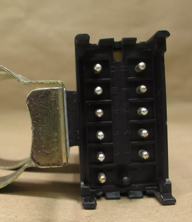
Now there is a terminating plug at the central lock controller, located in the frunk on the passenger side. That plug has the contacts from both microswitches as well as the central lock button and the actuators (motors in the doors) so we should be able to test here. The switches just connect the hot to ground (in either direction) and that should be testable with a partner and an ohm-meter or continuity tester. My DMM probes fit into the plug well enough that I was able to test the car alone.
Wiring detail for central locking: (MY 1988 shown)

From Bottom:
Controller Pin 6 (red) runs to low side of fuse 2, panel 1. (10 fuse panel)
Controller Pin 8 (black) runs to top side of fuse 6, panel 1. (" ")
The two Brown wires running from the door switches off the LH side are ground. (The poles)
Wires from the central lock switch are Yellow(12), Blue(11), Black/Blue(58) or Grey runs to interior lights, Brown (31) runs to ground.
There are 2 relays because we're flipping the polarity on the actuator in the door to make it go one way or the other. Connecting pins 5 to 7 actuates the relay closest to the connector. Pin 5 to 9 actuates the relay furthest from the connector. One is lock, the other is unlock. (added some links below about door lock circuits) I think the rest of the electrical bits are a timing circuit so it turns back off by itself. After testing out of the car, the relays stay on for about a second and then returns to rest. I think thats why the door actuators are shown as having a switch - they move and turn themselves "off" to keep state. That is my current guess, although my prior guesses were wrong so... I'm going try and trace it out to see what it is doing. (with a 12V bench supply, you can connect pin 5 to ground (neg), 6 to + and then use clips to connect 5 to 7 or 5 to 9 to energize the relays. )
Following the diagram (corrected), the 2 microswitches terminate on pins 5, 7 & 9 on the connector that runs to the central locking controller. 5 is the switch pole and is grounded, 7 & 9 are the microswitch connections to the controller. You can see the wiring details on connectors T32 & T33 which I believe are where the door harness connects to the main fton harness. The connector for the lock controller is not labelled.
The connector for the controller is a little tricky to get to, it is tucked in next to the radio antenna amp and behind other electrical & ventilation bits. The manual says to remove the M6 nut (and lockwasher) holding it in (10mm), which I needed a mirror to see at first. Then you can remove the header plug and test. I also removed the trim piece that covers the fresh air vents just to get a little more room. I really don't want to have to take apart both doors if I don't have to. I did purchase 2 microswitches and 2 sets of door handle gaskets just in case though. My logic is the doors probably see the most dirt & water, and if one switch is going, the other one is likely to go. I tend to overbuy parts because time is the thing I have the least of. YMMV.
I removed the nut and tried to work the controller gently out of the space under the windshield, but the circuit board was cracked and the cover just came off. It's not my first rodeo and I did not tug on the thing. The wiring is very tight though, and I am not sure what kind of work went on here in the past. But now I need a controller unit too unless I can epoxy the board and fix any broken traces.

Topside on the door controller. You can see the crack running parallel to end end plug here. Lots of diodes, the long blue things are resistor arrays, the chip is a quad op-amp. A few transistors. These are the standard relays Sachs seems to have used everywhere. It's a Siemens V23133, also a Tyco part number. I haven't yet seen one fail (yet) but just good info. They are not expensive and are still available.

The crack is much more visible underneath. Not convinced this is fixable even if I epoxy the board in place. The PCB is multi-layer so I also have to watch traces on top.

As you look at the bottom of the board, this can help visualize which pins are which.

4 to 3 are N/C, 4 to 5 are th N/O contacts. 1 & 2 are the coil.
A little detective work showed that the '88 & '89 have the same wiring pin-for-pin to the lock controller, and looking at photos online, the plug also appeared to be identical. (And it is) The difference in part # appears to just be for the mounting bracket. A new controller for the '88 is over $700 (ulp) but a used '89 controller on eBay was about $200, so I ordered it. It's also the same part as the '84-'91 944 as well.

1989 model

1988 model
1989 Model

1988 Model. The way the plug clips in is the same. The other little tabs are on the case.
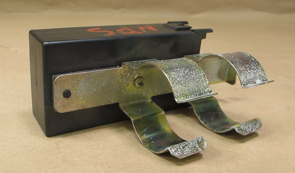
1989 Model bracket detail. It is screwed in as well as glued to a foam strip so if you need to change out the bracket you can use a razor to cut the foam off pretty cleanly.

1988 model bracket detail
I went out to the garage to see if I could test the doors while I wait for the controller. I used a very small standard screwdriver to gently pry it up without shorting anything. The plug is a bit stubborn to get off, but once it is off, the sockets are almost perfect for fitting a standard volt meter probe. I grabbed the car key, set the DMM for continuity (beeps on low ohm readings) and walked around the car to test both doors.

(Correction: microswtiches are on pins 5, 7 & 9) I got a little lost on the factory schematic but luckily I also have the Bentley which is simpler to read.
Passenger Side:
5 - 7 is CCW. This gave me a nice beep as long as I turned the key
5 - 9 is CW. This gave me a nice beep as long as turned the key
Driver's Side:
5 - 7 is CW (opposite side, opposite rotation). This gave me a nice beep as above.
5 - 9 is CCW. Nice long beep as above.
I am 99% sure that my door switches are ok - it seems unlikely that both doors would fail the same way, at the same time, and I do get continuity from both sets of contacts the same way.
So now I wait for the new controller to arrive. I'll either swap out the mounting bracket which is just held on by an external screw, or if it does not fit I can swap out the covers. And then hopefully I will have working door locks again.
New (used) controller(s):
It arrived just fine. It fits, the plug is identical. The case is identical so you can move the old bracket over. I plugged it in but nothing happened. It's been slow going between work and all the very cold days we've had recently. The only material difference is that the later bracket is glued on with some foam. Perhaps to dampen vibrations that were cracking the boards or to quiet any rattling? Not sure.
I have tested the connector from the chassis wiring: (all tested good)
Power from pin 6 to gnd (always hot)
Measure continuity from 5 to 7 and 5 to 9 for door switches when turned
Measure continuity between pins 11 & 12 when you push interior lock switch (beeps)
Measuring pins 3 to 4 should give DCR of the door motors. (very low ohms)
Pin 8 will have power only when key is in ACCY position.
That said, it does nothing. Like it is not getting power. I tested it on the bench to see if the relays would energize from the end pins (5 + 7 or 9, and 6), and they will not. I can power them directly on the PCB and they fire. So it is something upstream. I have to see about a return or credit because the eBay listing said it worked. That sucks.
I went back to the internet and found a slightly beat controller from a 944; the end of board connector that has the locating pin is missing and it can't snap into the case. But it was only $52 with shipping. It's easy to see which end is which (there is no pin 1 at all) so I plugged it in and now my locks bounce up and down again and won't stay locked. I am perhaps back to where I started? So that is something. I had thought that the crack in my PCB was causing the bouncing locks. But now it does not seem so? That end cap is also easy to swap between units, it comes right off. So my $52 controller likely a) works and b) I can get it into a good housing with a proper end cap so it will be 100%.
The resolution
I installed the $52 controller which had a bad case and a missing "end-pin plate" and initially the locks still bounced, but then it warmed up a bit and everything started working again. The issue may have been all cold-related, or a combination of cracked controller PCB and the cold. The connection to the internal door motor switch (pin 2 in particular) has no connection on my old controller. That is probably not helping.
I did some in-vitro testing of the controllers with a 12V bench supply. +12V to pin 6, neg to pin 5 (ground) and then connecting ground to pins 7 or 9 to simulate the door switches. The front* relay trips on pins 5 + 7, the rear relay trips on 5 + 9. Each relay only stays energized for about a second, so there is a timer of some sort. The motors in the doors also have switches inside them, which I now think is what is keeping state, essentially. The motor moves until it trips its own internal switch. And it has to reach full motion in about a second, while it has power, and if that doesn't happen maybe it keeps going until it gets back to rest where it started(?).
(* by "front" here I mean closest to the connector end)
Net net I wound up also buying a used actuator on eBay for $30 which fixed the issue of the passenger door not always unlocking properly unless the key was used in it. We'll see if these two fixes resolved all of our issues this winter.
Misc Circuit details:
I have not been able to find a schematic of the controller, and it's kind of an odd looking circuit. I am not sure what all the diodes are about. Recently I met a clever gent on the Pelican boards who has been through more of the electronics on these cars, and apparently Sachs were fond of diode based logic circuits. (see https://www.eeeguide.com/diode-logic-circuits/) which makes some sense if you need some "if / then" conditions to make the locks do certain things under certain conditions. The blue diodes are zeners (Vishay BZX85C series)
The board is covered in conformal coating to protect it from humidity and so it is very difficult to trace out since probes can't make contact through it and it's even hard to see through very well. I haven't found the right combination of solvent &/or heat to remove it, yet. But I have an intact dead one and a nearly working cracked PCB one so I'm sure I will find time to play with them. Worst case is I can remove the components from the "dead one" to ID them all and back into the connections on the board.
Parts wise it contains (approx)
9 Transistors (a mix of (3) BC337, (1) BC517, (4) BCX29 and one other I can't quite read. )
2 Siemens V23133 SPDT relays
1 quad Op-Amp LA6324
5 Electrolytic Caps (4.7uF/50V) 4 on board, one on connector card (I think, it's covered in epoxy)
7 resistor arrays (the blue things)
20 diodes (6 Zeners - the blue ones, 14 silicon diodes the "glass" ones here)
4 (5?) discrete resistors
1 other component up by connector that looks a resistor they needed away from the PCB, it is mounted vertically. My guess is that it can get hot.

The controller comes apart easily, too easily honestly, but swapping out housing parts is trivial.
References:
How power door locks work (ASE): https://www.freeasestudyguides.com/diagram-door-lock.html
Tech data on the relays: https://www.te.com/commerce/DocumentDelivery/DDEController?Action=srchrtrv&DocNm=V23133-X0000-A001&DocType=DS&DocLang=English
More detail on different door control systems:
Taking the door apart:
Central Locking:
Guide to the symbols that Porsche uses on their wiring diagrams
LA6324 Data sheet (High Performance quad op-amp)


Comments