Calibrating a cassette deck
- joepampel
- Jan 16
- 14 min read
Note: After reading the TapeOp article I changed the terminology for this post. They make a good case for "alignment" referring to the mechanical systems and things like head height and azimuth. Calibration is a more proper term for getting the electrical bits set properly.
I replaced the capstan motor, capstan belt & idler tire in my old cassette deck and cleaned the controls. Now it works, seemingly pretty well. But is it performing up to spec? Can it be better?
I purchased a couple of tools to make testing the deck possible:
a torque meter cassette - tests motor & transport health
a test tape - these come with pre-recorded test tones from a known good machine.
audio analyzer software - to simplify making the range of measurements
You will also need a good voltmeter and some tiny screwdrivers. A 4mm nut driver is what you'll need to adjust the azimuth. I'd reccommend finding one meant for RC vehicles, the tool needs to be small enough to get to the adjuster nut while the tape is playing.
Checking transport torque


Test Tape
I purchased a CrO2 calibration tape. Each formulation can have a different playback eq and level so to really do this properly you need 3 test tapes. 99% of my old cassettes are CrO2 so I just bought that one for now.
I bought this one on eBay from Raccoon labs:

The sections are:
Left and Right channel checks (6 seconds each). If you ran a repair shop, this would be your first test usually after power up. Do both channels even work? Do they perform differently? Are your cables reversed? ;) etc.
Next is 40 seconds of a 3kHz test tone to check tape speed
Test tones at 400Hz, 1kHz and 15kHz to check levels and azimuth
To test tape playback speed you simply play that section of the tape while using the software to check the output signal frequency. The pitch is usually either 3kHz or 3.15 kHz. If you're a musician without a test tape you can use a pre-recorded cassette that you know the key of and use your instrument to bring the deck into tune. Not perfect, but hey...
Checking the playback levels are pretty self explanatory.
Note: You do need to understand which dB scale your machine is using, which spec your test tape is using (how it was recorded) and finally which scale the software is using.
In the service manual you're told to measure the voltage at the output jacks and adjust adjust the playback level such that 0dB on the meters is .775V at the jacks. So it's really not that bad. That is assuming a Dolby standard cassette at 200nW/M.
dB level on a recorded tape is referenced to the magnetic flux used to record it. It's typically expressed in nano Webers per meter. That flux is what we see as recording level. Higher signal levels make a higher flux at the record head - the specs we discuss are where we are setting the 0dB mark on the VU meters.
In between the two extremes of tape noise and 3% THD (usually) is considered the tape's dynamic range. (see the 'how to set recording levels' link below)
The calibration tape I'm using states that it was recorded at 0dB ANSI (American National Standards Institute) which is 218nW/m. Dolby standard level is 200nW/m and is what the Denon service manual calls for. So a tape recorded at 200nW/m (0dB, Dolby standard) will put out .775V in this deck when properly adjusted.
The Denon service manual uses oddball units, because of course it does. They state a flux of 200 pwb/mn. What that is, is pico Weber per millimeter, and fortunately that is the same as nano Webers per meter. But why? No one uses that.
(see https://sengpielaudio.com/calculator-magneticflux.htm for some tables around fux vs dB levels)
You can calculate these levels easily though: 20 x Log (flux/185)
200nW/m = +0.68dB (over the Ampex 185nW/m 0dB standard)
218nW/m (ANSI - what my test tape uses) = +1.43dB
So the output from my ANSI recorded test tape should be (1.43-.68) = +0.75dB (over .775V) equals 1.09V
Audio testing software
After checking around a little, this app seemed like it would do what I needed and was only $24.95. They also made the dBX decoder app I'm using to restore my old 4-track tapes and it works well so I felt like this should be solid. It has been pretty good so far, certainly a great value.
Being an older hobbyist I have the analog versions of the gear I need for these tests, but this app nmakes the tests seamless to set up and run one after another; there is really no comparison. It also lets me test with pink noise and a spectrum analyzer, which I don't have.
Net net, I didn't sell out; I bought in.

To set up the app, you run L&R outs from your computer to your tape deck inputs, and then run your tape deck L&R outs to the inputs on your computer. Then you calibrate the deck & app - basically setting 0 dB to match on both. It's quick and simple. I have a UA Apollo recording interface on my Mac mini, so I needed to set it up for 'pass through' - no plugins, line in, no gain and I adjusted the routing so outputs 3 & 4 would be the returns to the deck (1 & 2 are the standard monitor outs). The output from the deck runs to the line inputs on the interface. With that done, I could calibrate the app with the deck using the provided instructions. It's basically getting both to read 0dB for a given signal so that the numbers line up when you test.
Checking speed and playback levels use a calibration cassette as a "known good" tape source. The test tone for speed is usually 3kHz, if it plays back at a higher frequency, your tape speed is too fast, etc. Tapes you record and play will be fine, it will really only affect tapes made on other machines or people playing back tapes you made on your machine. Some calibration tapes use slightly different frequencies so there is a "speed cal" mode to tell the app which frequency your tape is using. In a pinch if you are musician you can use a known good tape (pre-recorded) where you know what the key or chords are and put it up against your instrument or your ears.
Testing THD, wow & flutter and frequency response take advantage of having separate record and playback heads. [You can still run the tests if you have a 2-head deck, it's just a lot more work.]
The basic approach is you have the software send a signal into the deck, you record that signal live at some level on the meters (in "source" monitor mode) and then the deck is set to monitor the tape (not the source). That means the deck's output signal will be what is on the tape. By knowing what it is producing vs what it is getting back, the software can produce a number of measurements.
(demo video goes into this: https://youtu.be/5s7Kmr4HGuw)
Speed Measurement:
My test cassette features a 3kHz tone to test speed. My deck read 3,044Hz, so it was about 1.5% too fast. The service manual spec is 3,000Hz, +/- 6Hz which is +/- 0.2%. There is an adjuster screw on the back of the capstan motor for this that is located under a rubber dust cover. You adjust it while the calibration tape is playing. It uses a tiny trimmer potentiometer on the PCB for the motor which needs a small flat screwdriver. If you have one for installing a phono cartridge, that will do. A non-conductive one is ideal though.

Making the adjustment was a pain because the one spot it needs to be in has gotten worn over the years, from sitting still. I could get it to go a lot faster or a lot slower, but getting it between 2,994 and 3,006Hz was a genuine pain in the butt. But I got it there.

With the wow and flutter, the precise frequency moves up and down a little, but 3,003.9 is in range. As long as it does not go out of range you're good. (this was with the old motor which then died on me.)
Wow & flutter
The service manual calls for .04% RMS wow and flutter. This measurement came out a bit high (.086%) so I may need new pinch rollers. I can't hear it, but I guess it's there. There isn't an adjustment to make; if the transport is not working properly you need to track down which part(s) are to blame and address them. The pinch rollers are critical to a transport like this one and they are 40 years old. I'm not sure if these rollers can be replaced either, they come mounted on little stamped steel 'arms'.
It appears also that I may have reversed my capstans initially, so I swapped them around. The one with the rougher (matte) finish is now on the takeup reel. It does not seem to have helped the wow and flutter spec though. (my capstan motor was dying it seems)

TL;DR Alignment Process (Condensed from the service manual)
The TL;DR on order of operation is helpful I think. You start by using a calibration tape signal at 0dB to set the actual playback amp output level of the machine. Then you set the meters to match that, and then you can adjust the record circuits. It looks worse than it is in the manual.
Playback:
Use test tape 0dB tone playback to adj RT101 + RT201 for 0dB across line out (.775V). Just clip your voltmeter across one of the output channels one at a time. I would generally recommend using either 400Hz or 1kHz to make sure you don't encounter frequency response issues with your meter. If your tape is 0dB ANSI, you will want to see 1.09V.
RT101 (L)& 102(R) are the gain for the Playback EQ Amps. Block diagram below:

Meters:
Use test tape playback to adj RT401 & RT402 so that meter shows 0dB when Line out is 0dB
Recording:
Load a blank test recording tape, record 1kHz signal with input level of -41dB (I used -10dB on the meters)
Next, change signal to 12kHz. Record and playback.
Adj RT105 & RT205 so that the levels betweeen the two signals are equal
A better and simpler approach I used (I think) is to use the pink noise Freq spectrum test to get HF to line up (adj trimmers) and then check record levels and make sure both channels are still the same. You can do this live. Keep checking your THD as you go to make sure you are in the linear range for your tape.
Note: RT105 & 205 are setting the actual bias signal level for the tape. T301 is a transformer, to the left (off frame) is the actual oscillator. The full strength bias signal is fed to the erase head off of pin 8. Pin 9 gets split to give us L and R channel pots to set the bias level for recording our program material. The bias traps (RH) are filters to stop the bias signal from getting into the rest of the audio circuit. This deck uses a bias signal at around 105kHz.

Source/Tape monitor playback levels
Record 1kHz signal. (-41dB) on each type of tape and adjust RT102/202, RTR103/203 or RT104/204 so that monitor tape/source have the same level.
104 = Normal, 103 = CrO2, 102 = Metal


THD measurement (see readout below)
The total harmonic distortion ("THD") produced by the deck is largely influenced by the record bias level. Too much level and the tape will saturate and lose high end, too little and THD will get better - to a point, as will high frequency response. But there is finesse involved to balance these extremes. THD will get worse again below a certain level. THD can also make the high frequency response appear to get better.
Running a lower level to get better frequency response and lower THD also means your signal to noise ratio is worse - so the recording can sound hissy. No free lunch.
The exact type and formulation of the tape you are using affects this so you should calibrate with the tape you are planning to use.
Frequency Response of the unit:
The test suite produces a number of useful signals and sweeps to check the actual frequency response of the unit. Here you should use a blank tape of the type you plan to use to get the most useful results.
This particular deck is rated at 30-20,000Hz with Metal tape, +/- 3dB. It will be slightly worse on the high end with other tape formulations. But as long as it's not falling off before 12-15kHz we really won't notice much. The top octave is high harmonics for the most part, or "air" as it's sometimes called. -3dB is known as the half-power point, where the signal has literally lost half of it's power. It's also where the signal has shifted 45-degree in phase, (which is often what causes the loss of power. )
The Denon manual has you use test tones, which are fine. I prefer to test with pink noise; this gives you the whole frequency spectrum at once at an equal energy level and since the app has a spectrum readout you can see your frequency response change in real time as you adjust the machine. It literally could not be easier to adjust thanks to its 3-head configuration.
Type I (Normal) bias tape:
Here is the deck prior to alignment with the fine bias control at the midpoint, a type-I cassette and using Pink noise as the input signal. The recording is already ~3dB down by 8kHz roughly. No bueno. This would probably get published as 30-7kHz +/- 3dB. Ouch. The slope is 6dB per octave. This could also indicate the azimuth is off.

If I turned the fine bias adjustment all the way down without doing any calibration work, the frequency response improved; the -3dB point rose up to around 10 kHz (below). I'd like to see that up at 12kHz at least. I had the levels different on the two channels to see the differences more clearly. This kind of variation is typical; it's why manufacturers quote specs with descriptors like +/- 3dB ranges for frequency response.


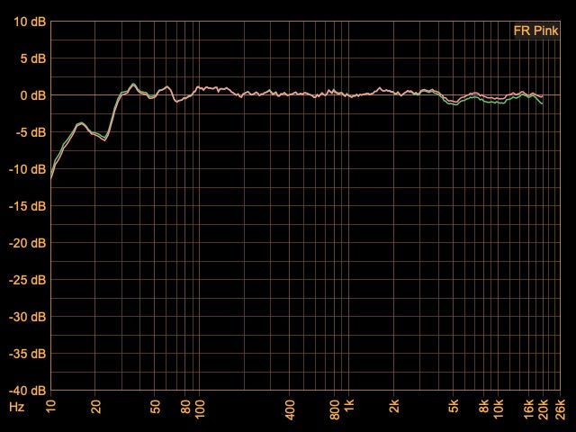
Above: Here are both channels after I ran through the alignment procedures playing back at the same level so they are overlaid. This is using Type-I tape and you can see both channels are nearly identical now and the high frequency response is a lot flatter through 20kHz (no noise reduction). Using pink noise as the signal you can align these readouts in real time on the display. Play with RT105/205 to see the effect on the high frequency response. Then toggle back to "basic" mode to see your THD reading.

THD at 400Hz is only .567% and the frequency response looks very solid so I'm almost there. Tape deck specs are usually quoted at 3% THD. Don't laugh; loudspeakers can get into the double digits. Here is the factory spec for S/N ratio, at 3% THD:

CrO2 tape (Type II)
Most of the process is the same, only the playback level adjustment changes due to the tape type. Here is where the TDK CrO2 tape ended up: (no noise reduction)

Head Azimuth
The time honored way to set playback head azimuth is to record a test tone on the two tracks furthest from each other and then monitor the recording. Each output is sent to an oscilloscope, one signal driving the vertical input and the other driving the horizontal input. The result is known as a lissajous curve. If the head is perectly in line with the tape (90 degrees), both audio tracks will cross the heads at the same moment. If the head is at an angle, the tracks will appear slightly out of time which will cause a difference in phase between the two signals. Humans cannot detect or hear absolute phase, but we can hear relative phase (A vs B) because it will create artifacts.
Perfect phase alignment between the channels will appear as a flat line sloping up to the right at a 45 degree angle. As the phase between the two signals goes out of alignment, that line becomes a wider and wider elipse. (see link below for more)
The good news with a home cassette deck is that the tracks are very close together so they can't get too far out, whereas a 2" 24 track machine can have real issues. Cassette tape is only .15"/3.81mm wide, and that .15" is divided into 4 tracks with space between them (Side A, L & R, and side B, L & R). The tracks on either side are .6mm each and .9mm center to center. Even so, at high frequencies you can have a lot of loss. One review of the Nakamichi Dragon quoted, "an error of 0.25 degree (one quarter of one degree, or 15 minutes) results in a response loss of 14.6dB at 15KHz and 25.5dB at 17KHz" (link below).
To throw a wrench into that, cassette deck heads aren't necesarily set to exactly 90 degrees. The tape is in a plastic case and alignment is not super precise. It can also change over time as the tape & shell wear. This is one reason the best decks use a dual capstan approach - to better control the tape alignment and speed as it moves past the heads. The deck itself may have a particular angle that sounds best which is not precisely 90 degrees.
In a "perfect" world the deck would adjust on a per-tape basis. This is what the Nakamichi Dragon actually did.
This is also an argument for using the approach to set the azimuth where you listen to program material (in mono) and tweak it for the best high frequency response. The issue again becomes about interoperability - will tapes made on other decks sound their best? Will tapes made on your deck sound good on other decks? There is a whole world of fun out there between speed, bias and head alignment.
Aside: It happened in professional studios too. The most well known example may be the song "Jet" by Paul McCartney & Wings. Relative to the rest of the album "Band on the Run", it is noticeably lacking in high end. This is because it was recorded at a different studio whose machine wasn't calibrated properly and they lost some high end. I thought something was wrong with my system the first time I played it.
So how did the ancient Denon do? Looks pretty good from here at 1kHz. It gets progressively worse as the frequency increases - about what you would expect - and the variation in the tape transport makes the phase reading jump around. (the dots)
The adjustment is also a tiny nut that is hard to get to, you need a 4mm nut driver with a very small head. I found one intended for RC toys that works well.
On nicer decks like the Nakamichis you can often adjust azimuth with a small screwdriver right from the front panel. Must be nice.
The signal is going up and to the left here because the signals are 180 degrees out, but it doesn't matter. We care about the 2 signals against each other. Normally though the display would go up to the right. This is just a phase flip in my interface, I think.


I hope this helps someone out, and if anyone catches an error or has a suggestion please let me know.
Resources:
Tape Op Article on tape machine calibration: https://tapeop.com/interviews/20/intro-analog-tape-deck-calibration-fun
Nak T-100 Audio Testing Software: http://www.anaxwaves.com/NAKT100/
Recording Tape comparision test: https://www.gammaelectronics.xyz/audio_06-1986_cassette-tapes.html
Nakamichi Dragon Review: https://www.hifi-classic.net/review/nakamichi-dragon-380.html
Convert gram force-cm to Nm: https://www.unitconverters.net/torque/gram-force-centimeter-to-newton-meter.htm
Terry's Rubber Rollers: https://www.terrysrubberrollers.com/
Tech Background:
How to set recording levels: http://www.ant-audio.co.uk/Tape_Recording/Library/Meters.pdf
Flux level on tape (calcs) https://sengpielaudio.com/calculator-magneticflux.htm
Lissajous curve: https://en.wikipedia.org/wiki/Lissajous_curve
Who was Weber? https://en.wikipedia.org/wiki/Wilhelm_Eduard_Weber
Cassette Tape dimensions: https://richardhess.com/notes/formats/magnetic-media/magnetic-tapes/analog-audio/015-cassettes/


Comments